Assembly
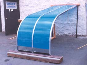
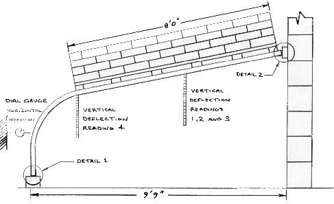
Description The test assembly is illustrated
below. As shown the test sunroom
consisted of three curved rafter sections
joined together by acrylic panels. The
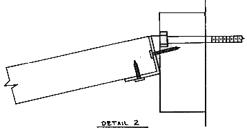
assembly was supported at the top end by
fastening the ledge angle into a timber 2
x 6 which was bolted to the concrete
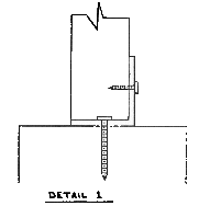
block wall and at the bottom end by an
angle fastened to a timber 6 x 6 fixed to
the asphalt pavement.
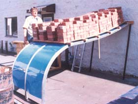
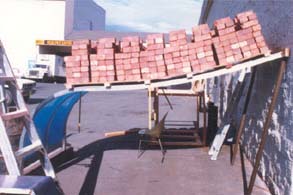
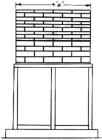
The
load was applied by stacking bricks onto
a plywood sheet which was supported on
six 2 x 4's on the aluminium rafters. The
weight of a representative sample of
bricks and the plywood was measured
before load application. The test
assembly deflection was measured at five
locations:
three vertical
movement monitors at the
approximate centrepoint of
each horizontal span
one vertical
movement monitor at the
curved end of the middle
rafter
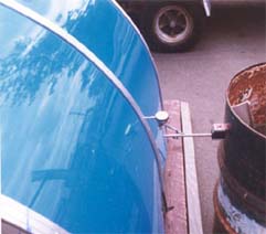
one horizontal
movement monitor at the
curved end of the middle
rafter
The test assembly construction
and load application was performed by Skyview Industries Ltd
personnel. The load and deflection monitoring was performed
by Hardy BBT Limited personnel.
Unloaded Test Assembly
Dial Gauge for Horizontal Deflection
Loaded Test Assembly
Loaded Test Assembly
Load Test Results
The test results are listed
in Table 1. Loading was continued until
it was observed that deflection occured under constant load. For
this test assembly it was undesirable to apply load to destruction
thus when creep deflection was observed, unloading was initiated.
The test assembly and loading are illustrated above. For convenience
the test results have been summarized below.
Subject: Results for the full-scale
load test performed on the 10 ft. span.